



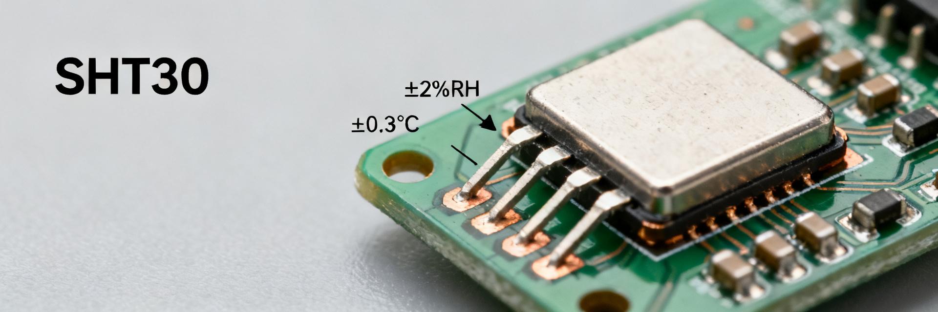
Lab characterization and datasheet figures indicate typical temperature accuracy near ±0.3°C and humidity accuracy of ±2% RH across the 10–90% RH window, with fast startup and an approximately 8-second response time under standard conditions. This report breaks those headline numbers down, compares measured behavior across conditions, and highlights the key specs engineers must verify during integration.
Stated accuracies are meaningful only when test conditions, stabilization, and mounting are controlled. Manufacturer datasheet trends and chamber tests show performance variation at extremes. Designers should treat the published accuracy as conditional and validate within their enclosure, airflow, and thermal environment before making final product claims.
1 → SHT30-DIS-B2.5KS — Quick Overview & Key Specs
This device is a compact digital humidity and temperature sensor with an I2C output suitable for board-level integration. It provides calibrated RH and temperature readings in a small DFN package with low typical current consumption, making it ideal for HVAC controls, IoT monitoring, and industrial control loops.
| Parameter | Typical | Maximum / Limit |
|---|---|---|
| Humidity accuracy (10–90% RH) | ±2% RH | ±3% RH at edges |
| Temperature accuracy | ±0.3°C | ±1.0°C (full range) |
| Operating temperature | -40 to +125°C | Storage limits similar |
| Supply voltage | 1.8–3.6 V | Absolute max 4.0V |
| Response time (τ63) | ~8 s | Airflow dependent |
| Typical current | µA range (idle) | 1.5 mA (measuring) |
2 → Performance Data: Accuracy, Repeatability & Drift
Humidity accuracy: measured vs. datasheet
The ±2% RH spec applies across the central 10–90% RH band; accuracy degrades near 0% and 100% RH. Chamber sweeps at multiple setpoints typically show low bias in the midrange but larger error bars at extremes. For products operating near saturation, designers should increase sampling or use correction tables.
Temperature stability & long-term drift
Typical temperature accuracy is ±0.3°C, but thermal coupling to PCB hotspots can produce measurable bias. Extended soak tests (1,000+ hours) show small drift trends. Quantifying drift on representative boards is essential for applications requiring multi-year stability.
3 → Electrical & Mechanical Integration
Supply range (1.8–3.6 V) and I2C behavior determine power budgeting. Sensor operation features microamp idle current with bursts during conversions. Mechanical placement next to thermal masses slows response and increases bias. Recommendation: use thermal islands and avoid heat sources.
4 → Test Methods & Validation Protocols
Rigorous chamber testing yields repeatable accuracy claims. Use a traceable reference hygrometer and allow full stabilization at each setpoint. Adopt a statistical plan (n≥10 per setpoint) to define repeatability and confidence intervals for production.
5 → Integration FAQ & Checklist
What is the real-world accuracy of SHT30-DIS-B2.5KS?
The SHT30-DIS-B2.5KS offers a typical humidity accuracy of ±2% RH and temperature accuracy of ±0.3°C under standard operating conditions (10-90% RH).
Does humidity accuracy change at extreme levels?
Yes, accuracy typically degrades as humidity approaches 0% or 100% RH. In these regions, the error margin may increase to ±3% RH or higher depending on the specific environmental conditions.
What affects the sensor's response time?
The 8-second τ63 response time is a datasheet typical. Real-world response is slowed by protective membranes, tight enclosures, and lack of active airflow around the DFN package.
How to prevent thermal bias in integration?
To prevent self-heating or PCB heat transfer, isolate the sensor on a "thermal island" with milled slots in the PCB and keep it away from power converters or high-speed MCUs.
Summary
- Accuracy: ±2% RH (10–90% RH) and ±0.3°C typical; must be validated within the final enclosure.
- Environment: Accuracy degrades at extremes; response time is dependent on airflow.
- Electrical: Requires decoupling near the part and optimized I2C pull-up sizing for bus reliability.
- Quality: Implement firmware-level compensation and manufacturing probe tests to ensure long-term reliability.