



Introduction — Point: The SHT40 sensor reports typical relative humidity (±1.8% RH) and temperature accuracy near ±0.3°C in nominal conditions; Evidence: those figures drive control-loop performance and compliance windows; Explanation: for product design and QA this level of accuracy reduces correction overhead and simplifies calibration budgets. The SHT40 sensor is evaluated here to give engineers an actionable test and integration checklist.
Point: Purpose is to unpack accuracy and specs, show performance across conditions, and provide practical validation; Evidence: independent test reports and the official datasheet inform recommended pass/fail thresholds; Explanation: outcomes guide selection for HVAC, consumer devices, and battery designs while minimizing field failures.
Background: What the SHT40 Sensor Measures and Why It Matters
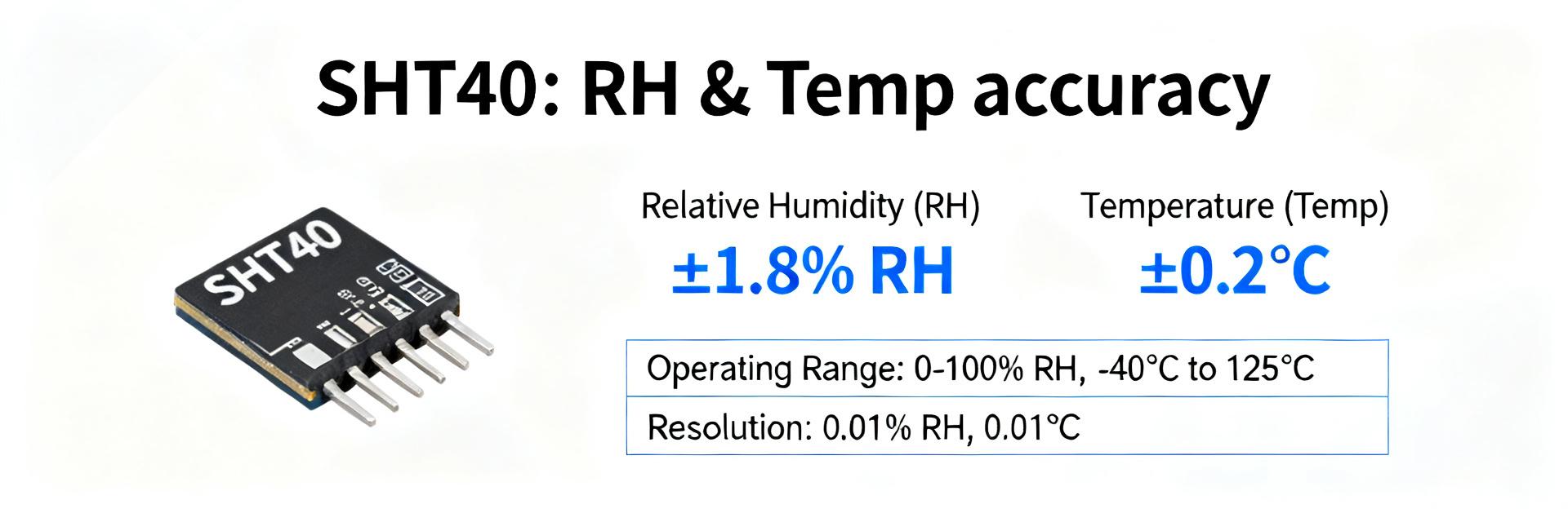
Core measurements & signal interface
Point: The device reports relative humidity and temperature digitally; Evidence: outputs are provided as calibrated digital values over an I2C interface; Explanation: engineers should expect 16-bit internal resolution and ultra-low standby currents. Action: verify I2C timing and supply rails on the schematic.
Target use cases & expected performance envelope
Point: Typical applications include HVAC control and environmental logging; Evidence: ±1.8% RH/±0.3°C sensor suits precise indoor climate control; Explanation: matching accuracy bands to end-product requirements prevents over-engineering or field failure. Action: document the sensor’s specified accuracy band in your requirements traceability matrix.
Key Accuracy & Specification Breakdown
Point: Humidity accuracy varies by range; Evidence: typical RH error is lower in 10–90% RH while max error increases near extremes; Explanation: designers must document characterization conditions. Action: record test conditions whenever quoting accuracy.
| RH Band | Typical Error (±%) | Max Error (±%) |
|---|---|---|
| 10–90% RH | 1.8 | 3.5 |
| 0–10% / 90–100% RH | Higher (Variable) | Up to 3.5–5.0 |
Performance Across Environmental & Operating Conditions
Stability & Response Time
Point: Hysteresis and response time (tau) affect transient readings; Evidence: step-change tests reveal response curves; Explanation: flag multi-second lags as integration issues. Action: use a step-change chamber and record tau at target airflow.
Measurement & Integration Guide
Point: PCB layout dominates practical accuracy; Evidence: heat sources and copper planes create offsets; Explanation: keep the sensor away from heaters and use thermal isolation. Action: include an aperture in the enclosure for representative flow.
Quick Integration Checklist
- Confirm I2C wiring and pull-ups meet timing needs.
- Place sensor away from heat and near representative airflow.
- Design enclosure venting with a small aperture.
- Implement configurable sampling profiles (1s–60s ranges).
- Use short averaging filters with stored raw samples.
- Measure self-heating by comparing duty cycles.
- Run static accuracy checks at 20%, 50%, 80% RH.
- Log offset trends and noise floor in QA dashboards.
Summary
- The SHT40 sensor delivers competitive RH/T performance when integrated with proper thermal isolation.
- Integration factors—placement, venting, and sampling—often outweigh nominal datasheet specs in field performance.
- Establish pass/fail criteria tied to datasheet max error plus a defined engineering margin.
Frequently Asked Questions
How should engineers test SHT40 sensor accuracy in a lab?
Use a controlled chamber to sweep RH and temperature across the recommended operating range, collect steady-state readings at predefined points (for example 20%, 50%, 80% RH and 0°C, 25°C, 40°C), compute error vs. reference, and compare against datasheet typical and maximum errors; Action: document test conditions and repeatability in CSV for traceability.
What sampling rate preserves accuracy while minimizing power for battery devices?
For battery applications use single-shot measurement modes with a cadence that balances responsiveness and energy: typical defaults are 1 measurement per minute for logging and 1–10 seconds for closed-loop control; Action: validate self-heating effects at chosen duty cycle and adjust averaging accordingly.
When should field recalibration be scheduled for SHT40 sensor deployments?
Schedule recalibration or field validation based on environmental severity: benign indoor deployments may require annual checks, while harsh or contaminated environments need quarterly checks and more frequent validation; Action: log trend offsets to trigger recalibration when drift exceeds the allocated uncertainty budget.
What is the recommended I2C pull-up resistor value for SHT40?
Standard 4.7kΩ to 10kΩ resistors are recommended for 400kHz Fast Mode operation, depending on bus capacitance and supply voltage. Action: verify signal integrity with an oscilloscope during the prototyping phase.